1-844-397-8677
The Main Components of a Concrete Pump
Posted On: 05/31/2023 | Posted by: DY Concrete Pumps
Understanding common concrete pump parts is an essential part of pumping concrete. Each component is essential to the process, allowing contractors to complete jobs safely and efficiently. Control circuits, spraying arms, air compressors, pipe systems, hoses, cleaning components, clamps and gaskets work together to help you finish projects and maintain your reputation.
The Importance of High-Quality Concrete Pump Parts
Construction is changing worldwide — urbanization has increased rapidly in recent years, meaning the need for efficient, practical construction is also rising. As ready-mixed concrete becomes more accessible, its many advantages will increase demand.
Construction requires efficiency. High work standards, increased project productivity and the ability to pump concrete into hard-to-reach places are crucial. A concrete pump and its components allow for faster and more consistent concrete distribution. Each of a concrete pump’s essential components leads to quality projects and repeat customers.
High-quality concrete pump parts are fundamental for operations. Using quality parts helps you complete jobs safely, effectively and efficiently.
The Working Principle of a Concrete Pump
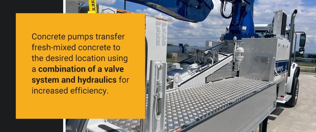
Concrete pumps efficiently transfer fresh-mixed concrete to desired locations using hydraulics and a valve system. The mixed concrete moves into a hopper, which continues the churning process to prevent solidification. The concrete pump sucks the liquid concrete out of the hopper using a valve system, then transfers it to where it needs to be.
A typical concrete pump contains twin hydraulic cylinders that work in tandem, pushing and pulling the concrete. The continual hydraulic concrete flow causes the cylinders to alternate back and forth and plays a vital role in preventing premature concrete solidification.
What Are Common Concrete Pump Parts?
A concrete pump has many components, and each is vital in pumping concrete effectively. Consider the following essential parts of concrete pumps.
1. The Main Pump Circuit
The primary pump circuit is one of a concrete boom pump’s most crucial parts. This circuit controls the parallel hydraulic drive cylinders and features the following components.
- Piston pump: The main hydraulic power pump gets its power from a variable displacement axial piston pump complete with a swashplate design. Adjusting the swashplate angle changes the stroke length of the pistons, and this process changes the concrete displacement. The more flow, the larger the swashplate angle becomes. Operators can adjust the swashplate angle using the load sense feature and the volume control.
- Motor: An engine or electric motor powers the main hydraulic pump. When the engine operates like usual, the pump switches off, minimizing the pressure on the pump and providing enough power to keep the pump lubricated.
- Valve manifold: A valve on the main circuit controls flow, the relief valve, the check valve and the pilot-operated directional valve.
- Throttle control: To energize the pump circuit, the operator sets the speed to maximum RPM using the throttle control.
- Cycling circuit: Once the pump switches on, it immediately triggers the cycling circuit. This circuit generates an electrical signal and activates the directional valves.
- Material cylinders: The two parallel cylinders alternately pump the concrete. Proximity sensors trigger the material pumping action, sending the signal from the sensors to the logic controller.
- Relief valve: This valve protects the primary pump circuit from extreme pressure. When the system pressure reaches the maximum allowed, the relief valve opens to let oil return to the tank.
2. The S-Tube Shift Circuit
This circuit controls the function for shifting the S-tube from one cylinder to the other during pumping. As there’s a single outlet for pumping material, there must be a method to transfer concrete from the cylinder to the outlet and then onto the delivery line.
The hopper has an S-tube to ensure task completion. There’s one S-tube for two cylinders, so it must be easy to shift from one cylinder to another. We can explain this circuit by considering each of the following components.
- Tandem pump: To meet pressure and flow requirements, a tandem pump installed in a single section of the shift circuit connects to the main hydraulic pump, which drives it.
- Manifold block: Just like the main hydraulic circuit, there are manifold blocks in the shift circuit.
3. The Auxiliary Circuit
The agitator’s hydraulic function is part of the auxiliary unit. The circuit controls the operation of the agitator and other additional equipment.
The agitator rotates to mix the concrete in the hopper and feed the cylinders. The tandem pump on the main circuit serves the auxiliary circuit. A solenoid cartridge or dump valve is a safety mechanism to prevent flow to the auxiliary circuit when the operator activates the emergency stop circuit.
One of the most significant functions of the auxiliary circuit is to assist in pumping concrete high in the air and over long distances. The main components of this system include the following.
- Elbow with wear-detecting holes: These holes in the concrete pump elbows consist of quench casting material. They smooth the ready-mixed concrete flow and increase safety and durability.
- Outrigger: This component hangs at an oblique angle and widens the overhanging area for more significant stable movement.
- U-shaped bottom of the hopper: This part facilitates the initial movement of the liquid concrete from the hopper into the intake port. Cleaning is more accessible due to the efficient flow of the ready-mixed concrete, as it reduces the remaining volume.
- Power-operated vacuum pump: This battery-powered vacuum pump minimizes pulsation and discontinuity in concrete flow. This component creates a more homogeneous mixture.
4. The Spraying Arm
The spraying arm positions the concrete flow at the correct location. Telescopic elevation platforms and scaffolding are unnecessary, as the component can spray for distances up to 56 feet. The spraying head mixes concrete, elevators and air. The nozzle dimensions and overall design are vital for ensuring minimal rebound and correctly incorporating the concrete.
5. The Air Compressor
The air compressor gives the concrete the kinetic energy to spray and compact. A specific velocity is necessary for shotcrete to impact the site’s surface, achieved with the compressor’s airflow and the correct nozzle diameter.
6. The Additive Pump
The accelerator meets the requirement for early strength development by speeding up the hardening of the concrete. The dosage depends on the concrete flow at all times. A synchronized dosing device, combined with the concrete pump, performs this function.
7. The Motorized Chassis
The motorized chassis transports the concrete pump to the desired location. The chassis design is crucial, as it needs to be able to turn in relatively small spaces and operate on uneven terrain.
8. The Control Panel and Remote Control
The control panel allows for ease of operation and confirms the condition of the ready-mixed concrete inside the hopper. Operators can control the pumping speed based on the operation’s needs. The digital display indicates when to perform maintenance checks or replacements.
Operators can use a remote control to manage the spraying process on site. Remote controls can be wireless or work via a cable connection and organize all the concrete components from one convenient location.

Additional Concrete Pump Parts
The following additional parts are also essential for proper concrete pumping.
Pipe Systems
Concrete pipes help contractors process concrete for projects, transfer it to work sites and deliver it to facilities safely and efficiently. Twin wall pipes are durable and specially designed for heavy-duty jobs. A twin wall pipe features a steel outer wall and a resistant inner lining that prevents corrosion and hardening. These features protect concrete and prevent it from hardening, allowing it to flow properly during distribution.
Hoses
Concrete pump hoses pump thick and abrasive substances such as concrete. A pump hose is durable and uses high pressure to pump concrete efficiently and safely. Their durability resists corrosion so you can complete jobs without inflicting damage.
Clean-Out Balls and Ball Catchers
Sponge foam clean-out balls are also important cleaning components because they help clear residue from the inside of pipes and hoses. After pumping concrete, you can use clean-out balls to clear debris, residue and remaining cement from the inside of concrete pump hoses. Clean-out balls have a parting stretch that enables them to move through narrow spaces without sustaining damage.
You also need a ball catcher when cleaning pipes. A pump pipeline might propel a clean-out ball, and you need something to stop it from flying across a work site. Remove the pump hose before securing the catcher and ensure the ball catcher fits the pipeline precisely.
Clamps and Gaskets
Concrete pump clamps connect and secure hoses to concrete pump boom pipes. Always use a pump clamp with a gasket to seal a hose and boom pipe connection.
Hose Pans
A hose pan reduces friction during pumping. Hoses can form bare patches when they surge forward and backward on the ground, but hose pans reduce friction to help the outer surfaces of hoses remain intact and last longer.
Safety Straps
Fit a concrete pump hose with a safety strap to keep it lifted and prevent it from falling. Ensure safety straps are in good condition to prevent them from malfunctioning or breaking. Purchase new durable safety straps if you notice your current straps are worn or damaged.
Reducers
A reducer is a pipe that can adjust to a smaller size. Reducers connect larger-diameter pipes to smaller-diameter pipes, which lessens flow. Using a high-quality reducer can help you achieve a steady stream for concrete pumping.
Contact DY Concrete Pumps Inc. for Your Next Concrete Pump
Using high-quality concrete pump parts helps your pump operate efficiently and increases its longevity.
If you want to increase your on-site efficiency or upgrade your concrete pump, DY Concrete Pumps Inc. can provide you with all the information you need to make the best choice for your business. Whether you’re looking for concrete boom pumps or line pumps, our extensive inventory has the ideal concrete pump to suit your operational needs.
As leading manufacturers in the industry with over three decades of experience, we can help you provide innovative and effective solutions for your clients. Contact us to learn more and upgrade your equipment today.